A
gear is a component within a
transmission device that transmits
rotational force to another gear or device. A gear is different from a
pulley in that a gear is a round wheel which has linkages, "teeth," that mesh with other gear teeth, allowing force to be fully transferred without
slippage. Depending on their construction and arrangement, geared devices can transmit forces at different
speeds,
torques, or in a different direction, from the power source.
The most common situation is for a gear to mesh with another gear, but a gear can mesh with any device having compatible teeth, such as other rotational gears, or linear moving
racks. A gear's most important feature is that gears of unequal sizes (diameters) can be combined to produce a
mechanical advantage, so that the rotational speed and torque of the second gear are different from that of the first.
In the context of a particular machine, the term "gear" also refers to one particular arrangement of gears among other arrangements (such as "first gear"). Such arrangements are often given as a ratio, using the number of teeth or gear diameter as units. The term "gear" is also used in non-geared devices which perform equivalent tasks:
"...broadly speaking, a gear refers to a ratio of engine shaft speed to driveshaft speed. Although
CVTs change this ratio without using a set of planetary gears, they are still described as having low and high "gears" for the sake of convention."
General The interlocking of the teeth in a pair of meshing gears means that their circumferences necessarily move at the same rate of linear motion (eg., metres per second, or feet per minute). Since rotational speed (eg. measured in revolutions per second, revolutions per minute, or radians per second) is proportional to a wheel's circumferential speed
divided by its radius, we see that the larger the radius of a gear, the slower will be its rotational speed, when meshed with a gear of given size and speed. The same conclusion can also be reached by a different analytical process: counting teeth. Since the teeth of two meshing gears are locked in a one to one correspondence, when all of the teeth of the smaller gear have passed the point where the gears meet -- ie., when the smaller gear has made one revolution -- not all of the teeth of the larger gear will have passed that point -- the larger gear will have made less than one revolution. The smaller gear makes more revolutions in a given period of time; it turns faster. The speed ratio is simply the reciprocal ratio of the numbers of teeth on the two gears!
(Speed A * Number of teeth A) = (Speed B * Number of teeth B)
This ratio is known as the
gear ratio.
The torque ratio can be determined by considering the force that a tooth of one gear exerts on a tooth of the other gear. Consider two teeth in contact at a point on the line joining the shaft axes of the two gears. In general, the force will have both a radial and a circumferential component. The radial component can be ignored: it merely causes a sideways push on the shaft and does not contribute to turning. The circumferential component causes turning. The
torque is equal to the circumferential component of the force
times radius. Thus we see that the larger gear experiences greater torque; the smaller gear less. The torque ratio is equal to the ratio of the radii. This is exactly the inverse of the case with the velocity ratio. Higher torque implies lower velocity and vice versa. The fact that the torque ratio is the inverse of the velocity ratio could also be inferred from the law of conservation of energy. Here we have been neglecting the effect of friction on the torque ratio. The velocity ratio is truly given by the tooth or size ratio, but friction will cause the torque ratio to be actually somewhat less than the inverse of the velocity ratio.
In the above discussion we have made mention of the gear "radius". Since a gear is not a proper circle but a roughened circle, it does not have a radius. However, in a pair of meshing gears, each may be considered to have an effective radius, called the
pitch radius, the pitch radii being such that smooth wheels of those radii would produce the same velocity ratio that the gears actually produce. The pitch radius can be considered sort of an "average" radius of the gear, somewhere between the outside radius of the gear and the radius at the base of the teeth.
The issue of pitch radius brings up the fact that the point on a gear tooth where it makes contact with a tooth on the mating gear varies during the time the pair of teeth are engaged; also the direction of force may vary. As a result, the velocity ratio (and torque ratio) is not, actually, in general, constant, if one considers the situation in detail, over the course of the period of engagement of a single pair of teeth. The velocity and torque ratios given at the beginning of this section are valid only "in bulk" -- as long-term averages; the values at some particular position of the teeth may be different.
It is in fact possible to choose tooth shapes that will result in the velocity ratio also being absolutely constant -- in the short term as well as the long term. In good quality gears this is usually done, since velocity ratio fluctuatons cause undue vibration, and put additional stress on the teeth, which can cause tooth breakage under heavy loads at high speed. Constant velocity ratio may also be desirable for precision in instrumentation gearing, clocks and watches. The
involute tooth shape is one that results in a constant velocity ratio, and is the most commonly used of such shapes today.
Mechanical advantage The definite velocity ratio which results from having teeth gives gears an advantage over other drives (such as
traction drives and
V-belts) in precision machines such as watches that depend upon an exact velocity ratio. In cases where driver and follower are in close proximity gears also have an advantage over other drives in the reduced number of parts required; the downside is that gears are more expensive to manufacture and their lubrication requirements may impose a higher operating cost.
The
automobile transmission allows selection between gears to give various mechanical advantages.
Spur gears Helical gears offer a refinement over spur gears. The leading edges of the teeth are not parallel to the axis of rotation, but are set at an angle. Since the gear is curved, this angling causes the tooth shape to be a segment of a
helix. The angled teeth engage more gradually than do spur gear teeth. This causes helical gears to run more smoothly and quietly than spur gears. Helical gears also offer the possibility of using non-parallel shafts. A pair of helical gears can be meshed in two ways: with shafts oriented at either the sum or the difference of the helix angles of the gears. These configurations are referred to as
parallel or
crossed, respectively. The parallel configuration is the more mechanically sound. In it, the helices of a pair of meshing teeth meet at a common tangent, and the contact between the tooth surfaces will, generally, be a curve extending some distance across their face widths. In the crossed configuration, the helices do not meet tangentially, and only point contact is achieved between tooth surfaces. Because of the small gagoarea of contact, crossed helical gears can only be used with light loads.
Quite commonly, helical gears come in pairs where the helix angle of one is the negative of the helix angle of the other; such a pair might also be referred to as having a right handed helix and a left handed helix of equal angles. If such a pair is meshed in the 'parallel' mode, the two equal but opposite angles add to zero: the angle between shafts is zero -- that is, the shafts are parallel. If the pair is meshed in the 'crossed' mode, the angle between shafts will be twice the absolute value of either helix angle.
Note that 'parallel' helical gears need not have parallel shafts -- this only occurs if their helix angles are equal but opposite. The 'parallel' in 'parallel helical gears' must refer, if anything, to the (quasi) parallelism of the teeth, not to the shaft orientation.
As mentioned at the start of this section, helical gears operate more smoothly than do spur gears. With parallel helical gears, each pair of teeth first make contact at a single point at one side of the gear wheel; a moving curve of contact then grows gradually across the tooth face. It may span the entire width of the tooth for a time. Finally, it recedes until the teeth break contact at a single point on the opposite side of the wheel. Thus force is taken up and released gradually. With spur gears, the situation is quite different. When a pair of teeth meet, they immediately make line contact across their entire width. This causes impact stress and noise. Spur gears make a characteristic whine at high speeds and can not take as much torque as helical gears because their teeth are receiving impact blows. Whereas spur gears are used for low speed applications and those situations where noise control is not a problem, the use of helical gears is indicated when the application involves high speeds, large power transmission, or where noise abatement is important. The speed is considered to be high when the pitch line velocity (that is, the circumferential velocity) exceeds 5000 ft/min.
A disadvantage of helical gears is a resultant thrust along the axis of the gear, which needs to be accommodated by appropriate
thrust bearings, and a greater degree of sliding friction between the meshing teeth, often addressed with specific additives in the lubricant.
Helical gears  Double helical gears
, invented by
André Citroën and also known as herringbone gears, overcome the problem of axial thrust presented by 'single' helical gears by having teeth that set in a 'V' shape. Each gear in a double helical gear can be thought of as two standard, but mirror image, helical gears stacked. This cancels out the thrust since each half of the gear thrusts in the opposite direction. They can be directly interchanged with spur gears without any need for different bearings.
Where the oppositely angled teeth meet in the middle of a herringbone gear, the alignment may be such that tooth tip meets tooth tip, or the alignment may be staggered, so that tooth tip meets tooth trough. The latter type of alignment results in what is known as a
Wuest type herringbone gear.
With the older method of fabrication, herringbone gears had a central channel separating the two oppositely-angled courses of teeth. This was necessary to permit the shaving tool to run out of the groove. The development of the Sykes
gear shaper now makes it possible to have continuous teeth, with no central gap.
Double helical gears Main article: Bevel gear Bevel gears  A crown gear
 A crown gear or contrate gear is a particular form of bevel gear whose teeth project at right angles to the plane of the wheel; in their orientation the teeth resemble the points on a crown. A crown gear can only mesh accurately with another bevel gear, although crown gears are sometimes seen meshing with spur gears. A crown gear is also sometimes meshed with an escapement such as found in mechanical clocks.
Crown gear Hypoid gears resemble spiral bevel gears, except that the shaft axes are offset, not intersecting. The pitch surfaces appear conical but, to compensate for the offset shaft, are in fact hyperboloids of revolution.
 Hypoid gears
 Main article: Worm gear Worm gear Main article: Rack and pinion Rack and pinion Rack railway See also 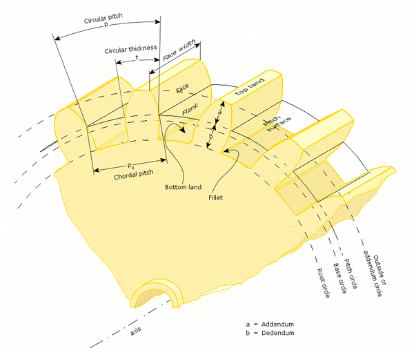
Common abbreviations
- n. Rotational velocity. (Measured, for example, in r.p.m.)
ω Angular velocity. (Radians per unit time.) (1 r.p.m. = π/30 radians per second.)
N. Number of teeth.
Path of contact. The path followed by the point of contact between two meshing gear teeth.
Line of action, also called 'Pressure line'. The line along which the force between two meshing gear teeth is directed. It has the same direction as the force vector. In general, the line of action changes from moment to moment during the period of engagement of a pair of teeth. For involute gears, however, the tooth-to-tooth force is always directed along the same line -- that is, the line of action is constant. this implies that for involute gears the path of contact is also a straight line, coincident with the line of action -- as is indeed the case. Further note on tooth force
Axis. The axis of revolution of the gear; center line of the shaft.
Pitch point (p). The point where the line of action crosses a line joining the two gear axes.
Pitch circle. A circle, centered on and perpendicular to the axis, and passing through the pitch point. Sometimes also called the 'pitch line', although it is a circle.
Pitch diameter (D). Diameter of a pitch circle. Equal to twice the perpendicular distance from the axis to the pitch point. The nominal gear size is usually the pitch diameter.
Pitch surface. For cylindrical gears, this is the cylinder formed by projecting a pitch circle in the axial direction. More generally, it is the surface formed by the sum of all the pitch circles as one moves along the axis. Eg., for bevel gears it is a cone.
Angle of action. Angle with vertex at the gear center, one leg on the point where mating teeth first make contact, the other leg on the point where they disengage.
Arc of action. The segment of a pitch circle subtended by the angle of action.
Pressure angle (ø). The complement of the angle between the direction that the teeth exert force on each other, and the line joining the centers of the two gears. For involute gears, the teeth always exert force along the line of action, which, for involute gears, is a straight line; and thus, for involute gears, the pressure angle is constant.
Outside diameter (Do). Diameter of the gear, measured from the tops of the teeth.
Root diameter. Diameter of the gear, measured from the base of the tooth space.
Addendum (a). The radial distance from the pitch surface to the outermost point of the tooth. a = (Do - D) / 2.
Dedendum (b). The radial distance from the depth of the tooth trough to the pitch surface. b = (D - root diameter) / 2.
Whole depth (ht). Addendum plus dedendum; or, equivalently, half the difference between the outside diameter and root diameter.
Clearance. The amount by which the dedendum of a gear exceeds the addendum of the gear it is mating with.
Working depth. The depth of engagement of two gears. It equals the sum of their addenda.
Circular pitch (p). The distance from one face of a tooth to the corresponding face of an adjacent tooth on the same gear, measured along the pitch circle.
Diametral pitch (Pd). The ratio of the number of teeth to the pitch diameter. Eg., could be measured in teeth per inch or teeth per centimeter.
Base circle. Applies only to involute gears, where the tooth profile is the involute of the base circle. The radius of the base circle is somewhat smaller than that of the pitch circle.
Base pitch (pb). Applies only to involute gears. It is the distance from one face of a tooth to the corresponding face of an adjacent tooth on the same gear, measured along the base circle. Sometimes called the 'normal pitch'.
Interference. Contact between teeth other than at the intended parts of their surfaces.
Interchangeable set. A set of gears, any of which will mate properly with any other.
Helical Gears:
- Helix angle (ψ). The angle between a tangent to the helix and the gear axis. Is zero in the limiting case of a spur gear.
Normal circular pitch (pn). Circular pitch in the plane normal to the teeth.
Transverse circular pitch (p). Circular pitch in the plane of rotation of the gear. Sometimes just called "circular pitch". pn = p cos(ψ).
Several other helix parameters can be viewed either in the normal or transverse planes. The subscript " n " usually indicates the normal.
Worm gears:
- Lead. The distance from any point on a thread to the corresponding point on the next turn of the same thread, measured parallel to the axis.
Linear pitch (p). The distance from any point on a thread to the corresponding point on the adjacent thread, measured parallel to the axis. For a single-thread worm, lead and linear pitch are the same.
Lead angle (λ). The angle between a tangent to the helix and a plane perpendicular to the axis. Note that it is the complement of the helix angle which isusually given for helical gears.
Pitch diameter (Dw). Same as described earlier in this list. Note that for a worm it is still measured in a plane perpendicular to the gear axis, not a tilted plane.
Subscipt " w " denotes the worm, " g " denotes the gear. Gear nomenclature
Backlash is the error in motion that occurs when gears change direction. It exists because there is always some gap between the tailing face of the driving tooth and the leading face of the tooth behind it on the driven gear, and that gap must be closed before force can be transferred in the new direction. The term "backlash" can also be used to refer to the size of the gap, not just the phenomenon it causes; thus, one could speak of a pair of gears as having, for example, "0.1 mm of backlash." A pair of gears could be designed to have zero backlash, but this would presuppose perfection in manufacturing, uniform thermal expansion characteristics throughout the system, and no lubricant. Therefore, gear pairs are designed to have some backlash. It is usually provided by reducing the tooth thickness of each gear by half the desired gap distance. In the case of a large gear and a small pinion, however, the backlash is usually taken entirely off the gear and the pinion is given full sized teeth. Backlash can also be provided by moving the gears farther apart. For situations, such as instrumentation and control, where precision is important, backlash can be minimised through one of several techniques. For instance, the gear can be split along a plane perpendicular to the axis, one half fixed to the shaft in the usual manner, the other half placed alongside it, free to rotate about the shaft, but with springs between the two halves providing relative torque between them, so that one achieves, in effect, a single gear with expanding teeth. Another method involves tapering the teeth in the axial direction and providing for the gear to be slid in the axial direction to take up slack.
Backlash
See epicyclic gearing
In an ordinary gear train, the gears rotate but their axes are stationary. An epicyclic gear train is one in which one or more of the axes also moves. Examples are the sun and planet gear system invented by the company of James Watt, in which the axis of the planet gear revolves around the central sun gear; and the differential gear system used to drive the wheels of automobiles, in which the axis of the central bevel pinion is turned "end over end" by the ring gear, the drive to the wheels being taken off by bevel gears meshing with the central bevel pinion. With the differential gearing, the sum of the two wheel speeds is fixed, but how it is divided between the two wheels is undetermined, so the outer wheel can run faster and the inner wheel slower on corners.
Epicyclic gearing
In some machines (e.g., automobiles) it is necessary to change the gear ratio to suit the task. There are several ways of doing this. For example:
Manual transmission
Automatic gearbox
Derailleur gears which are actually sprockets in combination with a roller chain
Hub gears (also called epicyclic gearing or sun-and-planet gears)
Continuously variable transmission
Transmission (mechanics) Shifting of gears
As mentioned near the beginning of the article, the attainment of a non fluctuating velocity ratio is dependent on the profile of the teeth. Friction and wear between two gears is also dependent on the tooth profile. There are a great many tooth profiles that will give a constant velocity ratio, and in many cases, given an arbitrary tooth shape, it is possible to develop a tooth profile for the mating gear that will give a constant velocity ratio. However, two constant velocity tooth profiles have been by far the most commonly used in modern times. They are the cycloid and the involute. The cycloid was more common until the late 1800s; since then the involute has largely superseded it, particularly in drive train applications. The cycloid is in some ways the more interesting and flexible shape; however the involute has two advantages: it is easier to manufacture, and it permits the center to center spacing of the gears to vary over some range without ruining the constancy of the velocity ratio. Cycloidal gears only work properly if the center spacing is exactly right. Cycloidal gears are still used in mechanical clocks.
Tooth profile
The cage gear, also called lantern gear or lantern pinion, has been used for centuries. Its teeth are cylindrical rods, parallel to the axle and arranged in a circle around it, much as the bars on a round bird cage or lantern. The assembly is held together by disks at either end into which the tooth rods and axle are set.
Cage gear
Numerous nonferrous alloys, cast irons, powder-metallurgy and even plastics are used in the manufacture of gears. However steels are most commonly used because of their high strength to weight ratio and low cost.
Gear materials
Earle Buckingham, Analytical Mechanics of Gears; 1988, Minneola, New York, USA; Dover. First copyright 1949 by Earle Buckingham. This is an influential treatise on gears. Advanced Level.
Venton Levy Doughty and Alex Vallance, Design of Machine Members, 4th edition; 1964; McGraw Hill. First edition was 1936. This is an engineering text on machine parts. It has two chapters on gears.
McGraw Hill Encyclopedia of Science and Technology. 2002.
Notes
No comments:
Post a Comment